
Whether you’re trying to troubleshoot power-related issues or check the hardware compatibility of a device, understanding the ATX power supply pinout is the gateway to dive into.
Ever since Intel introduced the ATX standard, users can effortlessly combine hardware from different manufacturers without having to worry about power supply connectors compatibility issues.
However, there might be cases when you have to troubleshoot your PSU. For instance, You have tried everything there is to fix your broken PC and now you want to check for power supply problems. In such cases, having a solid foundation of the ATX power supply pinout is vital.
In this article, I will emphasize on the functionality of each of the pins on the 24-pin ATX power connector but along with that, I’ll also make sure you’ll get a general insight on the pinout of other connectors.
24 Pin ATX Power Connector Pinout
The 24 pin ATX connector is used to power your motherboard including other on-board components like RAM, chipsets and NVMe SSDs.
While it has a standard configuration of 24 pins, some manufacturers still provide an old 20 pin configuration plus detachable 4 pin configuration for enhanced compatibility. The additional four pins were introduced later to provide extra power for motherboards and meet the PCI Express power requirements.
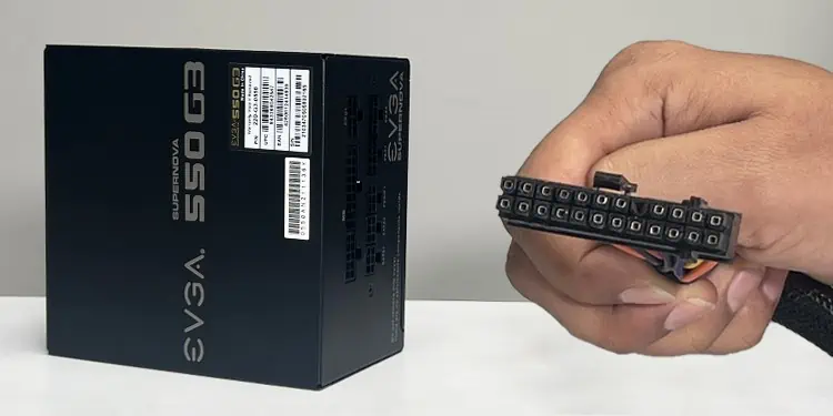
Below is the (20+4) pin ATX connector that came with my EVGA Supernova 550 G3 PSU. I can effortlessly connect this type of connector to the motherboard header that has either a 24 pin or a 20 pin setup.

Here’s a quick overview of the ATX power connector pinout.

Each of these pins on the connector have a specific purpose on your system. Let’s now dive straight into them.
+5VSB
This is the pin that supplies standby power to your system even when it is turned off. It facilitates multiple useful features like Wake-on-LAN and Wake-on-USB when your computer is in a low-power state. It also comes into action when you first turn on the computer. More on this later.
PS_ON#
This pin is particularly used to turn on the power supply unit of your computer.
Technically speaking, when your computer is connected to the AC wall outlet, the +5VSB pin already starts supplying standby power to the system.
So, when you press the power button on the computer, a small voltage triggers the PS_ON# pin. As such, the pin will go low (connects to the ground,) which in turn, signals the PSU to turn on.
Additionally, the PS_ON# pin is also highly useful for troubleshooting the power supply. You can disconnect the ATX connector from your motherboard and use a paperclip to connect the PS_ON# (pin number 16) to GND ( pin number 15.) If the power supply is functioning properly, it should turn on.

PWR_OK
When the PSU is first turned on, it takes a short time to stabilize the output voltage. Once stabilized, the power supply unit sends a PWR_OK signal to the motherboard, indicating that the power supply is now stable and within acceptable limits.
Your motherboard will refuse to turn on if it does not receive the PWR_OK signal.
+3.3V DC
There are four +3.3V DC pins in the ATX power connector that supplies 3.3V DC power to your motherboard.
If you inspect the connector carefully, you will also find that one of the 3.3V DC pins (pin number 13) has two wires entering it as seen in the image below.

While the first one is for power supply, the second one exists there for sensing the voltage levels. It is actually used to calculate the difference between the expected and actual voltage levels. If any discrepancy is found, the PSU will make necessary adjustments.
+5V DC
There are a total of five +5V DC pins on the ATX power supply connector. As you might have already guessed, this pin particularly supplies 5V DC power to your system including on-board storage disks like SSDs, and other peripheral devices.
+12V DC
Unlike the +3.3V and +5V pins, there are only two +12V DC pins on the ATX power connector. The motherboard’s VRM (Voltage Regulator Module) converts this 12V to a range of voltage levels and supplies it to other PC components.
-12V DC
The ATX power connector includes a -12V DC pin that was responsible for supplying negative voltage to legacy ports like RS-232 and legacy audio circuits in the early days. The pin is still integrated in the modern day connectors to power a part of the PCI bus.
COM
There are a total of eight COM pins on an ATX power connector which act as a ground or reference point for all other voltage pins.
Not only does it provide the referencing, but also check voltage fluctuations and helps mitigate the electrical noises and interferences.
NC
If you look closely, you will find that one of the pins (pin number 20) is missing from your ATX power connector. This is actually the “No connection” pin.

However, there used to be a -5V DC pin instead of the NC ones in the old school connectors. It was typically used to power the legacy ISA devices like sound card, graphic card or a modem installed into the ISA expansion slot.
CPU Connector Pinout
As the name suggests, this connector is particularly used to power the CPU. It either has a 4, 8, (4+8,) or (8+8) pin configuration and the pinout differs depending upon the connector type.
Here I will be discussing the pinout for the standard 8 type connector that came with my EVGA Supernova 550 G3 PSU.

As you can see, the 8 pin CPU connector simply has four pins for 12V rails and four others for ground. If your CPU only uses four pins, it will have two pins for 12V rails and the other two for grounding purposes.
SATA Connector Pinout
The serial ATA (SATA) connector powers the SATA interface devices, like a SATA hard drive or SSD including some other peripherals like a RGB controller.
It has a standard 15 pin configuration in a special L-shaped housing, to simplify the connection process. Despite the 15 pins on the connector, you will only see 5 wires entering into the connector. Below is a quick overview of its pinout.

These voltage rails are used to supply power to a range of electronic components within the SATA devices.
Coming to the voltage rails, the 3.3V and 5V ones are generally used to power low-power components like a SSD memory module and HDD controller.
On the other hand, the 12V rail powers the high-power components like a spindle motor in your hard disk.
PCIe Connector Pinout
Used to power GPUs, these connectors come with a standard 8 pin setup that are generally detachable into (6+2) blocks.

As you can see in the image above, the 8 pin PCIe connector has three pins for 12V rails, three for ground and the remaining two for voltage sensing.
The sense pins in these connectors are used to monitor the power requirement of a GPU so that the power supply unit can adjust the voltage levels accordingly.
On the flip side, you won’t be getting the same pinout if your GPU utilizes only 6 pins for connection. It, instead, has two 12V rails, two ground wires and one sense wire. The remaining one may either have “No connection” or another 12V rail depending upon the manufacturer.
While in connectors from some manufacturers, you may not get the sense wires at all. They just have three pins for 12V and five pins for ground (in 8 pin setup) and three 12V pins and three GND pins (in 6 pin setup.)
Molex Connector Pinout
And here comes the last one in our list, the Molex connector. This type of connector is used to power the legacy devices having Molex interface. For instance, a PATA hard drive, or a CD/DVD drive.
Coming to its pin configuration, it generally has a four pin setup in a single row. But some variants may include four pins arranged with two pins in each row.
Here’s a brief overview of the common Molex connector pinout.
